5. Solar Car Regulations
5.1 Physical Regulations
5.1.1 Dimensions
All solar cars entered will have the following maximum dimensions: length = 5 meters; height = 1.6 meters; width = 1.8 meters. Minimum height is 1 meter. When turning corners, wheels and wheel fastenings may exceed these dimensions. Fins, antennas, and other aesthetic components may not be used to meet the minimum height requirement. Antennas may extend above the maximum height requirement.
5.1.2 Stability
To ensure stability under various road conditions, the vehicle must employ either a three or four wheel design. If a three wheel design is used, event officials strongly suggest that the single wheel should be in the rear of the vehicle, with two wheels in front. Regardless of the number of wheels chosen, it is recommended for vehicle stability that the ratio of the track (distance between the front wheels, measured at the center point of the tire footprint) to the wheel base (distance from front to rear wheels, measured at the center point of the tire footprint) be no less than 0.5 to 1.0. In other words, the track should be no less than one-half the wheel base. In addition, it is recommended that the vehicle track to total vehicle height be no less than 1:1. During scrutineering, cars must demonstrate the stability of the vehicle. Any of the wheels may be powered, but front wheel(s) must be used to steer the vehicle.
5.1.2.1 Suspension
Suspension components must be properly rated for the weight of the solar car. Improperly rated suspension components can lead to unstable handling and potential for roll-over. As such, suspension components must not exceed 50% of travel when fully loaded.
5.1.3 Body of the Vehicle
Although windshields are required, solar cars need not have a body or covering unless the event judges determine that the driving of that vehicle would be unsafe and/or create an unreasonable risk of harm to the driver. Solar cars are required to have a belly pan sufficient to protect the driver.
5.2 Structural Safety
Safety is the sponsor’s primary concern with regard to the structural development and fabrication of the solar cars. Insufficient regard for structural safety will result in disqualification from the event during scrutineering
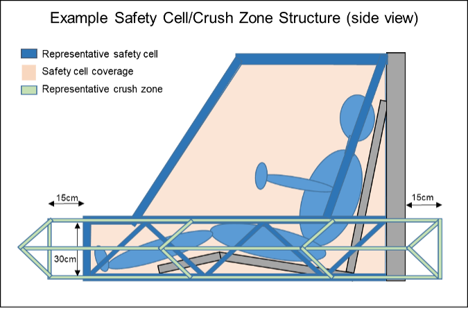
In specific, solar cars must be constructed with three codependent structural safety components: a safety cell structure near the driver, a separate crush zone structure on the outside of the safety cell, and a roll bar. All structures must be designed to help protect the driver in the event of collision. The safety cell structure is intended to be constructed with heavier material so that it does not deform during the collision whereas the crush zone structure can be constructed with lighter material so that it gives way without deforming the safety cell and absorbs the energy of the impact.
5.2.1 Safety Cell
All solar cars must be equipped with a safety cell that provides rigid protection encompassing the entire driver’s head, torso, legs, and feet. The purpose of the safety cell is to provide a solid structure that protects the driver and prevents intrusion of objects into the driver compartment. The safety cell shall be a fixed, integral part of the solar car structure. The protection provided for the driver in a collision must be documented in the team's mechanical drawings. In addition to providing collision and rollover protection, the safety cell must be designed so as to deflect body/array panels of the car away from the driver in the event of an accident
5.2.1.1 Minimum Dimensions
The safety cell tubing must have a minimum outside diameter of 1.9 cm. There must be at least 5 cm of clearance in all directions between the safety cell and the driver seated in the normal driving position. Teams must demonstrate at scrutineering that each driver complies with the 5 cm clearance
5.2.1.2 Coverage
If the safety cell was to be wrapped in an elastic fabric, no part of the driver should touch the fabric. The arms may extend out of the safety cell when holding the steering wheel
5.2.1.3 Padding
The safety cell, including the roll bar, must be padded with a high density padding wherever a driver may likely contact it in a collision (e.g. heads, knees, elbows)
5.2.2 Roll Bar
The roll bar is a distinct structural member that is a key part of the safety cell. The roll bar extends above the driver’s head, protecting the driver in the event of a roll-over. The roll bar must consist of one continuous piece of metal. The bottom of the roll bar must extend at least 5 cm vertically from the top of the driver’s head or helmet
Solar cars where the driver’s head rises above the top of the solar car body must have an additional roll bar to deflect the body component over the driver in the event of a collision.
5.2.2.1 Welded to Frame
The roll bar must be welded to the frame at no less than two points on each side of the driver to brace the bar from bending forward or backwards. The roll bar must be an integral part of the frame and cannot be removed
5.2.2.2 Minimum Dimensions
The roll bar tubing must have a minimum outside diameter of 5 cm. It must also have a minimum wall thickness of 1.0 mm for chromoly steel, 1.5 mm for carbon steel, and 3.2 mm for aluminum
5.2.3 Crush Zone
A crush zone is defined as structural components outside of the safety cell that are designed to collapse in an effort to absorb some of the impact from a collision without impacting the driver space. The crush zone must provide driver and battery protection from front, side, and rear collisions.
5.2.3.1 Minimal Horizontal Distance
There must be crush zone structural components at least 15 cm of horizontal distance away from the outside of the safety cell in every direction (front, sides, and rear). Teams must demonstrate that all drivers comply with this regulation when seated in normal driving position.
5.2.3.2 Minimum Vertical Distance
Left side and right side crush zone structures must be at least 30 cm tall and encompass the driver’s lower torso.
5.2.3.3 Grandfathered Cars
Cars entered in the 2022 event or prior may have crush zone structural components at least 15 cm of horizontal distance away from the driver in every direction and encompass the driver’s head, upper, and lower body, upon formal request and with explicit permission from the Event Director. It is intended that this provision be removed after the 2025 event.
5.2.4 Composite Material
The use of composite materials is permitted on the solar car. However, if composite materials are used in the safety cell, roll bar, or crush zone, the team must send a sample of the materials to a professional organization specializing in destructive testing to verify adequate structural strength and submit the resulting report to Event Officials for evaluation.
5.3 Solar Array
Global solar radiation received by the car directly from the sun is the only power source that will be stored or used for propulsion.
5.3.1 Solar Cell and Array Size Limitations
Solar cell types are restricted by division and set out in Section 10. For all vehicles, the solar array may be configured in any way, provided that the size of the array fits within the maximum dimensions of the solar car. When stationary, the solar array may have any orientation to the sun. The solar array must remain mounted on the outside of the vehicle, except as provided in Section 5.3.4. The solar array cannot be dismantled and carried inside the vehicle.
5.3.2 Array Configuration
The solar array cannot be reconfigured, without specific written permission of the Event Director. Reconfiguration is defined as changing the position or orientation of any portion of the array. Changing the position or orientation of the entire array, when stationary, is not considered reconfiguration. When stationary, the array may exceed the maximum height of the solar car so long as the array is not reconfigured.
5.3.3 Reflector
No reflector-type device can be used to enhance the collection capacity of the panel.
5.3.4 Umbilical Cord
To position a solar car’s solar array in a favorable position for charging, an umbilical cord may be used. This cord must be carried on the solar car. The purpose of the umbilical cord is to provide the racing participant the means to keep the array electrically connected to the vehicle, though physically removed from the vehicle to receive more favorable sunlight. Teams reconfiguring only a portion of the array must request explicit permission for reconfiguration, as required in Section 5.3.2.
5.4 Battery
In the interest of cost and standardization, only rechargeable, commercial production, lead-acid or lithium iron phosphate (LiFePO4) batteries are permitted (unless otherwise allowed in Section 10). The total battery capacity cannot exceed 5.25 kilowatt-hours at a 20 hour discharge rate (for lead-acid) or at a 1C discharge rate (for LiFePO4). There is no limit applied to system voltage, number of cells, or modules. Manufacturer documentation must be provided for all battery types.
5.4.1 Main/Propulsion Battery System
Solar cars must be equipped with main/propulsion batteries to power the solar car. The main/propulsion battery system must be completely isolated from the supplemental system of the solar car. The main/propulsion battery pack may not be used to power anything other than propulsion devices or devices associated with the main/propulsion battery system (such as a battery management system).
5.4.1.1 No Battery Reconfiguration
Once the event has begun, the batteries in the main/propulsion battery box cannot be reconfigured without specific written permission of the Event Director. Reconfigured is defined as changing the connectivity of the individual batteries in the main/propulsion battery system.
5.4.1.2 Exceeding Capacity
Capacitors can not be used to supplement the 5.25kwh battery capacity. Batteries may not be “supercharged” to exceed the 5.25 kWh limit. “Supercharged” is defined as exceeding 16% of the nominal battery voltage (e.g. charging 12 volt nominal batteries to voltages over 14 volts).
5.4.1.3 Battery Protection
Lithium-chemistry batteries, including LiFePO4 batteries, must be protected by a Battery Management System (BMS) monitored at the cell level.
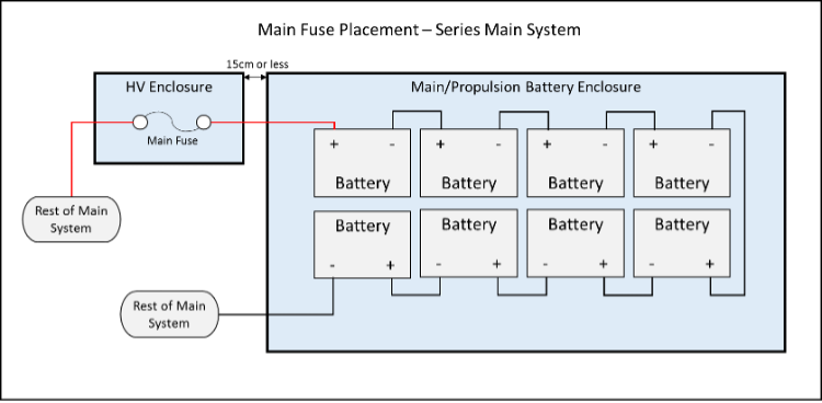
5.4.2 Main Battery Pack Fuse
The main battery pack fuse must be placed first in series off the positive terminal of the main/propulsion battery system. (See subsequent diagrams for details.)
(a) When the battery pack fuse has been blown, the positive side of the Main Battery Pack must be completely isolated.
(b) Main Battery Pack Fuse must be rated for the appropriate DC voltage. AC voltage ratings shall not be used to determine proper rating.
(c) Main Battery Pack fuse must be rated for no more than 125% of the expected peak current draw.
(d) Main Battery Pack fuse must be placed in an enclosure (hereafter “HV enclosure”) separate from any battery enclosures or power tracker enclosures that will completely contain the fuse in the event of an aggressive failure of the fuse. The HV enclosure must be no more than 15cm from the outside of the Main/Propulsion Battery box where the lead exits the battery box.
(e) Manufacturer documentation must be provided for the Main Battery Pack fuse.

5.4.3 Battery Enclosure
The main battery pack must be fully contained in enclosures that can be sealed by event officials (thus sealing the batteries). A hasp latch for the battery enclosure will assist event officials in complying with this section of the rules
(a) A battery enclosure is defined as a rigid box-like structure constructed from materials that are not easily flexible and that provides protection and stability to the battery system in the event of collision. Battery bags are not allowed.
(b) Batteries need to be strapped down, or held in place using structural members so that they will not move in the event of a vehicle roll over. If conductive materials are used to fasten batteries inside of the battery enclosure they must be properly insulated.
(c) The inside surfaces of battery enclosures made from conductive materials must be completely insulated.
(d) Battery boxes must be located within the crush zones as defined in Section 5.2.3. As such, battery boxes must not be located at the front of the vehicle frame.
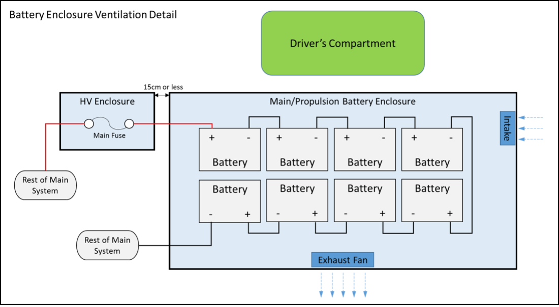
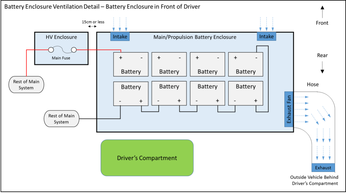
(e) Other than forced air ventilation system intake and exhaust, the battery box must be air tight. Neither the intake nor exhaust may be open to the driver’s compartment.
(f) Battery boxes for lead-acid batteries must have forced-air ventilation which must operate whenever the battery system is electrically connected to the solar car, that maintains negative air-pressure within the box, cycles the air in the box 4 times per minute, and vents to the outside of the vehicle behind the driver’s compartment. [See diagram below] There must be at least 3 cm of clearance between any devices inside the battery enclosure and both the intake and exhaust of the battery enclosure to ensure necessary room for air flow. Neither the intake or exhaust may be open to the driver’s compartment; ducting the exhaust behind the driver’s compartment is acceptable.
(g) Each battery and the battery box must be securely fastened to the vehicle’s structure so that the box will not move in the event of a crash. Nylon straps can be used to help secure the battery box; Velcro does not meet this requirement.
5.4.4 Supplemental Batteries
All solar cars must be equipped with supplemental batteries to power solar car accessories requiring an external power source, such as, but not limited to, electronic speedometers, cameras, memory devices, telemetry transmission, and battery box fans, and they must be totally isolated from the propulsion system of the solar car. Telemetry systems may have a common ground with the propulsion system, as long as the current draw is low.
(a) Battery Type There are no regulations limiting the type, voltage, or weight of supplemental batteries.
(b) Low Battery Warning System The supplemental batteries powering the following equipment: (1) lights; (2) horn; and (3) battery box air circulation fans, must be equipped with a low voltage warning system that will aggressively warn the driver with an audible alarm when the supplemental battery pack is getting low.
(c) Proper Mounting Supplemental batteries must be securely fastened to the vehicle’s structure so that the batteries will not move in the event of a crash or vehicle roll over. Nylon straps can be used to help secure the batteries; Velcro does not meet this requirement.
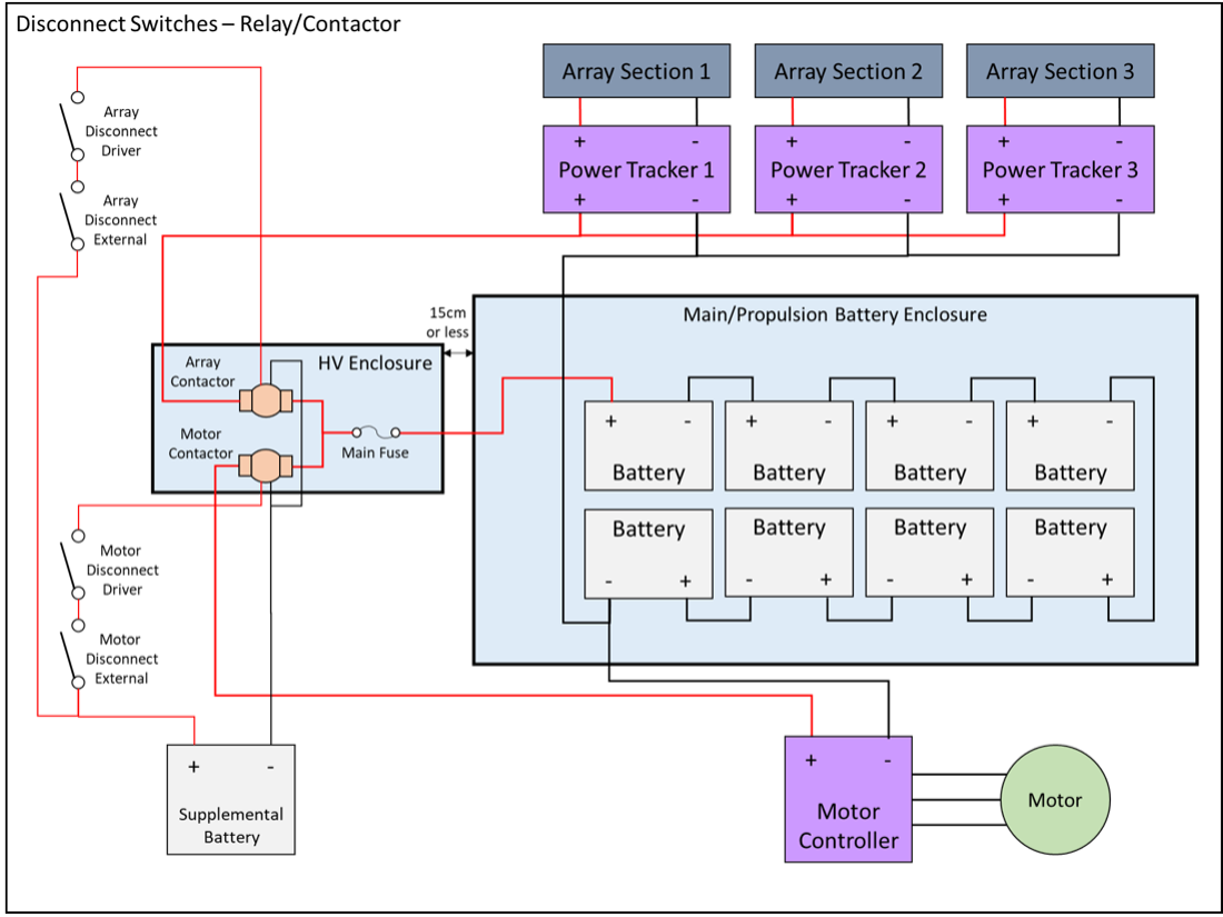
5.4.5 Disconnect Switches
Solar cars must have “kill” switches and relays/contactors wired to disconnect all power to the motor and solar array. A total of four disconnect switches are required two each to interrupt current to the motor and array. One set of motor and array disconnects shall be accessible by the driver, within arm’s reach, and another set shall be accessible by bystanders external to the vehicle. The motor and array disconnect switches must operate the associated relay/contactor (motor or array) that is located within the HV enclosure, as described in Section 5.4.2. Relays/contactors must be continuous duty, normally open, and capable of carrying and interrupting the full load current at system voltage.
(a) Disconnect switches must be push-pull, where the circuit is broken when the disconnect switch is pushed in.
(b) Disconnect Switches must be clearly labeled in 10mm-high letters, and be plainly marked with “ON” and “OFF” positions. Motor disconnect switches shall be labeled “Motor Disconnect” and array disconnect switches shall be labeled “Array Disconnect” Switches shall be labeled with the directions for operating the switch, such as “Push for Off.”
(c) Manufacturer documentation must be provided for all disconnect switches and relays/contactors and show that the devices being utilized are rated properly.
(d) Disconnect switches and relays/contactors must be securely fastened to the vehicle structure to prevent failure in emergency situations.
(e) Disconnect switches must be in plain sight by a bystander in standing position and may not be hidden under panels.
(f) Relays/contactors must be in series with no other devices or connections between them. The motor relay/contactor shall be placed first in series on the positive connection to the motor controller. The array relay/contactor shall be placed first in series on the positive connection to the solar panels or solar array power trackers, if used.
5.5 Electrical System Grounding
Neither the main/propulsion system nor the supplemental system may be grounded to the vehicle’s frame. Electrical system grounding shall mean that a resistance of less than 1 MΩ between electrical components and the vehicle’s frame when voltage is applied.
5.6 Assistance Devices
Any device used to assist the start, stop, or powering of a solar car must be carried on the solar car and must be a permanent part of the electrical system. Once the event has started, teams will not be allowed to plug any devices into the solar car except telemetry equipment and multimeters.
5.7 Wire, Insulation, and Connections
5.7.1 Wire
All wires must be properly rated for voltage and temperature. Wires must be properly sized to expected continuous system current. Wires must be properly and neatly secured to prevent movement or snags during solar car operation. Wires must be secured by a protective grommet when passing through a bulkhead. No wire conducting more than 36 volts may be located within the driver’s compartment.
5.7.2 Insulation
All electrical connections must be insulated using techniques that will withstand the temperatures and vibrations they are exposed to while operating a solar vehicle. Heat shrink and battery caps are the preferred method for insulation. Electrical tape shall not be used to insulate any propulsion system wires.
5.7.3 Connections
All electrical connectors must be rated for voltage, amperage, and temperature. Connections must be able to handle the vibrations they will encounter during when driving a solar car on the road. All connections conducting more than 36 volts must be properly secured with locking washers. Wing nuts and wire nuts of any type are not acceptable connecting techniques on a solar vehicle.
5.8 Seating Position
Each occupant must be provided with an appropriately constructed seat where the occupant’s head is higher than his or her feet. [See Section 5.13(j)]
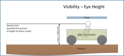
5.9 Visibility
In the normal driving position, each driver's eyes must be a minimum of 70cm above the ground. All visibility rules must be met with the driver securely fastened into their harness in a normal driving position.
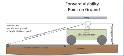
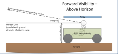
5.9.1 Forward Visibility
From the normal driving position, all drivers must be able to see, without artificial assistance:
- a point on the ground 8 meters in front of the solar car
- A minimum of 10 degrees above the horizon on level ground.
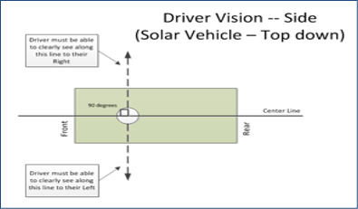
5.9.2 Side Visibility
From the normal driving position, all drivers must be able to see, without artificial assistance, 90 degrees to either side at all times. This must be essentially unobstructed by the solar car structure. The intent is for the driver to see oncoming traffic, left and right.
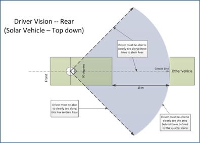
5.9.3 Rear Visibility
All solar cars must be equipped with a rear vision system that will allow the driver to see a vehicle 15 meters directly behind the solar car, as well as see vehicles 45 degrees in each direction approaching from the rear. If an electronic rear vision system is used, it must operate whenever a driver is present in the vehicle.
5.10 Braking
The intent of the sponsor is to require that solar cars be capable of braking and coming to a safe stop based upon road and traffic conditions. To this end, solar cars will be equipped with two separate braking systems. This means that there must be two separate foot pedals (one for each braking system) that are connected to an independent actuating device. Automotive style foot brake pedals must be used; teams cannot repurpose other braking devices (e.g. motorcycle hand brakes, 3D printed pedal). The two separate foot pedals may not be linked together and must each operate stop lights. Each braking system must apply brakes to the left and right sides of the solar car evenly. Regenerative brakes are not considered a braking system for consideration in this rule. During scrutineering, solar cars will be required to demonstrate their braking capability at both 20 mph and at the vehicle’s maximum speed.
Low Speed At 20 mph, the driver must be able to bring the vehicle to a safe, controlled stop in no more than 2.5 seconds. High Speed At the vehicle’s maximum speed, the driver must be able to bring the vehicle to safe, controlled stop without drifting out of the appropriate lane of travel, and within a reasonable time frame based on that vehicle’s maximum speed.
5.11 Steering
All steering must be directly operated by the driver with a steering wheel that is round and has a continuous perimeter. All components between the driver's steering wheel and wheel turning mechanisms must be connected via direct mechanical linkages. No electrical actuators or controls are allowed.
5.11.1 Turning Radius
Solar car wheels must be able to make a U-turn in a 15-meter wide lane in each direction.
5.12 Warning Systems
5.12.1 Lighting
Solar cars must have stoplights, front and rear turn indicators, and hazard lights. The geometric visibility of each light should be 45 degrees from center and 15 degrees up and down.
(a) Stop lights must be red in color. Turn indicators and hazard lights must be amber in color.
(b) Stop lights must be visible at 100 meters and mounted to maximize rear visibility. All other lights (front/rear turn indicators and hazard lights) must be visible from 30 meters away.
(c) Stop lights must be pedal activated by both primary and secondary braking systems.
(d) At the event official’s discretion, teams may receive a “moving violation” for each incidence of non-working lights. Once the team is notified by an event official that they have a non-working light, they must safely remove themselves from the official course and make the necessary repairs.
(e) On cross-country races, both chase vehicles must be equipped with four amber ECCO 3510, ED3511 or 3811 warning lights.
5.12.2 Audible Warning
Drivers must be able to give audible warning to pedestrians and other vehicles using a horn producing at least 92 decibels as measured at the source. The horn shall be mounted as far to the front of the vehicle as possible and face forwards. The horn may not be located inside the passenger compartment. Air horns may not be used as a horn device. In closed-track events, the horn must be sounded when a solar car attempts to overtake and pass another vehicle. .
5.13 Driver Safety
Teams must take whatever steps necessary to protect the safety and well-being of the drivers. Driver safety measures include, but are not limited to:
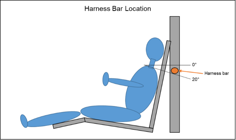
(a) Safety Belts - Solar cars must be equipped with a minimum of a five-point lap and shoulder belt (harness system). The use of safety belts is mandatory at any time the vehicle is moving. The belts must be attached securely to a structural component or main frame member of the solar car, per manufacturer’s instructions, with bolts at least SAE Grade 8 and 3/8” in diameter. Shoulder belts must be mounted to a harness bar that is between 0 and 20 degrees lower than the driver’s shoulders. No belt shall be punctured in order to mount it to the solar car.
(b) Impact Protection - The driver compartment must be equipped with structural components that help protect the driver from vehicle roll-over, or from front or side impacts, in compliance with Section 5.2 (above). All sharp objects and frame members within the driver area must be padded to help protect the driver during entry and egress and in case of impact.
Teams with body shells are required to have the shells securely attached to each other to reduce the threat of injury in the event of a collision.
(c) Protection from Vehicle Components - All equipment housed within the vehicle must be adequately secured to the main frame to prevent the shifting of that equipment during an impact. Special emphasis is placed on securing the batteries due to their weight and potential for environmental damage.
(d) Windshield - All solar cars will utilize windshields at all times to protect the driver from road hazards. Windshields must provide protection for the entire head of the driver.
(e) Cockpit Egress - Each driver must be able to demonstrate that unassisted egress can be achieved in less than 15 seconds in the event of an emergency. The “exit process” will be carefully checked by event officials during scrutineering. Other team members cannot assist the driver during this required “exit process.”
(f) Fire Extinguishers - Cockpits must be equipped with a Class C fire extinguisher which can be easily reached by the driver in the event of an emergency. Chase vehicles must also be equipped with either a Class C fire extinguisher (for lead-acid batteries), a Class D fire extinguisher (for Lithium-metal batteries), or an appropriate fire extinguisher for other battery chemistries.
(g) Liquid Container - Cockpits must be equipped with a plastic liquid container filled with water, which can be easily reached by the driver. The liquid container must be secured from movement such that it cannot roll underneath the brake and throttle controls.
(h) Belly Pan - The cockpit must be equipped with a full belly pan to isolate the driver from the road. The belly pan consists of a solid material resistant to puncture throughout the driver compartment.
(i) Air Circulation - Forced air ventilation must be provided for the solar car’s driver. This is particularly important for the health and safety of the driver while the vehicle is powered but not in motion. This requirement applies whether or not the driver’s compartment is enclosed or open.
(j) Driver Seat - When the driver is seated in the normal driving position, the driver’s seat must provide back and neck support for the driver, such that whiplash will be minimized in case of an accident or sudden stop. The seat must be rigid and attached to main structural frame using at least SAE Grade 8 bolts 3/8” in diameter. Seats mounted on adjustable rails must be mounted to a seat back brace that is attached to the safety cell or roll bar.
(k) Battery Spill Kit - A battery spill kit consists of a box of baking soda, to mitigate the effects of battery spills. All teams must carry a battery spill kit in the solar car, within reach of the driver. All teams must also carry a second battery spill kit in their chase vehicle.
5.14 Throttle
Accelerator mechanisms on solar cars must be free moving and when released, must return to the zero current position. If the solar car is equipped with cruise control, it must be designed with an automatic shut-off when the brake is activated. Solar cars may only be equipped with a cruise control system during closed-track events. All accelerator mechanisms (manual throttle or cruise control) must be directly operated by the driver. At least one accelerator mechanism must be foot-operated.
5.15 Covers and Shields
The solar car’s revolving parts, such as, but not limited to chains and belts, must be suitably covered to prevent accidental contact by the driver. All steering linkage must be shielded from the contact of the driver. If a flywheel is used, it must be covered by a National Hot Rod Association-approved shield.
5.16 Electrical Shock Hazards
All conductors must be properly insulated. All conductors operating at greater than 36 volts must be marked with “High Voltage” warning signs. All solar cells and panels must be marked with “High Voltage” warning signs. All leads extending from the solar array must be properly protected to eliminate accidental shock hazards resulting from participants or bystanders coming in contact with these leads. Event Officials strongly suggest the following steps to improve safety:
- When working with the battery box, be sure that you only use one hand, and that the other hand is kept behind your back. In the event of an electrical shock, the charge will not pass through the entire body.
- When working with the battery box, be sure to use rubberized tools to insulate against the possibility of electrical shocks.
- Students working in the battery box require continuous supervision by teachers or chaperones.
- When working with the battery box, be sure to wear eye protection (a full face shield is best) to protect against battery explosions caused by sparks or arcing.
5.17 Radios
Solar cars must be equipped with a two-way radio to allow communication with the chase vehicle. Teams must demonstrate during scrutineering that the transmission from the solar car can be received at a distance of at least 0.5 miles. If a radio system “goes down” during the event, drivers must stop at the earliest opportunity and make repairs before proceeding on the course. Judges will make every effort to ensure that a team’s radio communications will remain private, unless there is a safety issue involved.
5.18 Fasteners
All fasteners associated with the vehicle’s suspension, steering, brakes, seat belts, and drive train must be equipped with locking nuts, double nuts, or nuts secured with safety wire or cotter pins. Loctite may be used in areas of difficult accessibility. When nylon locking nuts are used, the bolt must extend past the nut by at least two threads.
5.19 Graphics
5.19.1 Inappropriate Graphics
The event organizer reserves the right to disapprove any graphic it deems offensive.
5.19.2 Sponsored Graphics
Teams must reserve a space 10" (horizontal) by 10" (vertical) on both sides of the vehicle for official event graphics. The sponsor graphics location should be near the front of the solar car.
5.20 Tires
All tires must be loaded and inflated per manufacturer’s guidelines. No tire may be inflated at pressures higher than what is written on the tire’s sidewall or manufacturer’s data sheets.
5.21 Waivers
Teams may request a waiver for the specific solar car regulations [See Section 5]. Teams must submit a waiver request to the Event Director before May 1. Waivers may not be requested at scrutineering. The waiver request must document the rule number the team requests waived, the proposed alternative that meets the intent of the rule, and engineering analysis that shows the alternative satisfies the intent of the rule. Detailed mechanical drawings (in three views) or electrical schematics may be required to fully document the proposed alternative. Waiver requests may be electronically submitted to the Event Director, so long as the request is saved in Microsoft Word or Adobe PDF format. Waivers issued for previous years are invalid; teams must resubmit a waiver request for each event year.